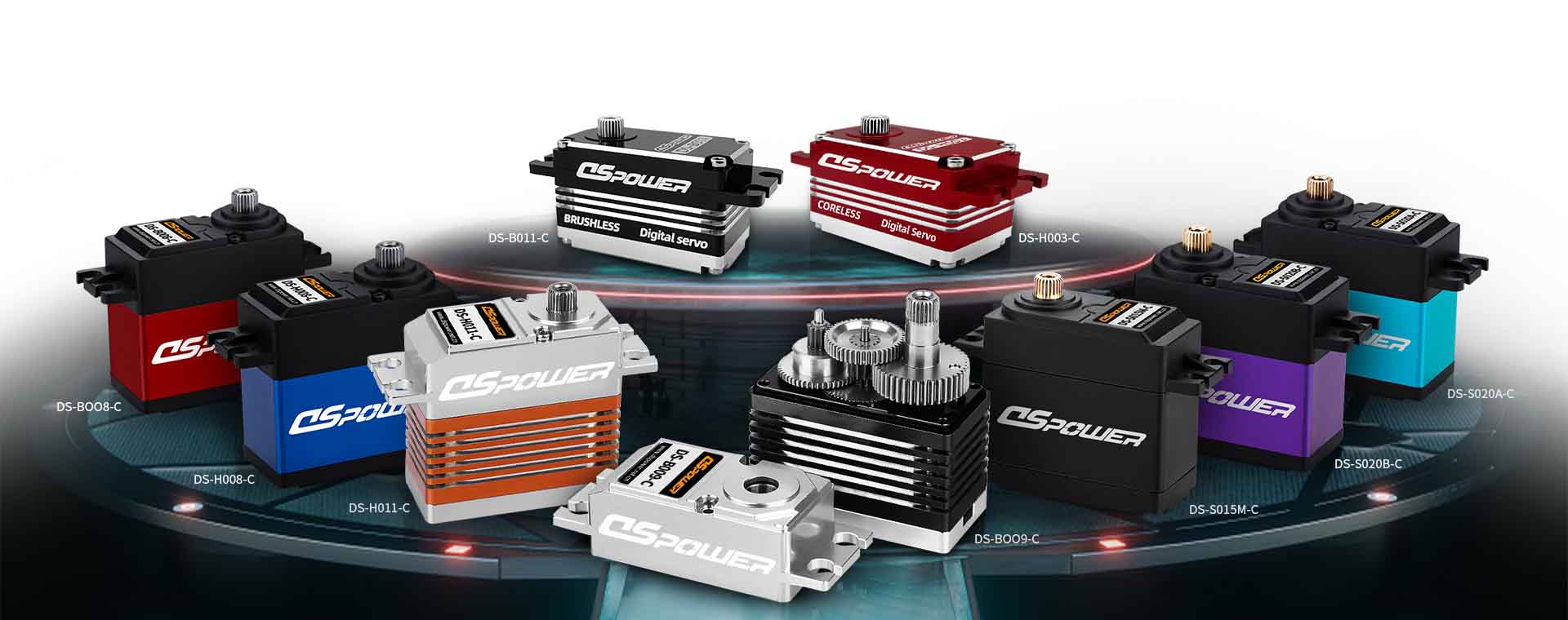
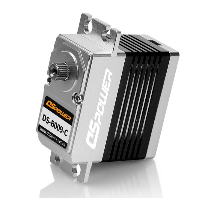
A servo (servomechanism) is an electromagnetic device that converts electricity into precise controlled motion by use of negative feedback mechanisms.

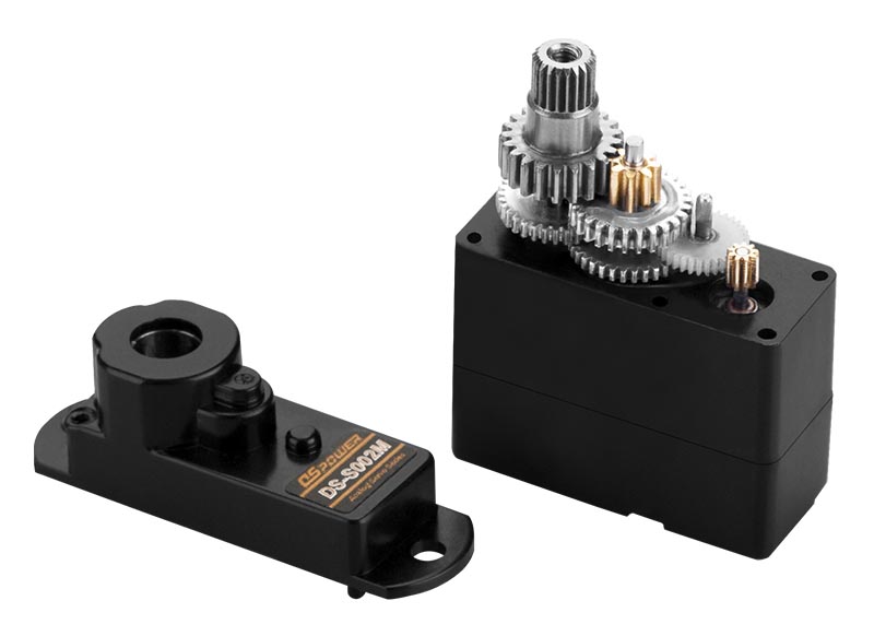
Servos can be used to generate linear or circular motion, depending on their type. The makeup of a typical servo includes a DC motor, a gear train, a potentiometer, an integrated circuit (IC) and an output shaft. The desired servo position is input and comes in as a coded signal to the IC. The IC directs the motor to go, driving the motor’s energy through gears that set the speed and desired direction of movement until the signal from the potentiometer provides feedback that the desire position is reached and the IC stops the motor.
The potentiometer makes controlled motion possible by relaying the current position while allowing for correction from outside forces acting on control surfaces: Once the surface is moved the potentiometer provides the signal of position and the IC signals the necessary motor movement until the correct position is regained.
A combination of servos and multi-geared electric motors can be organized together to perform more complex tasks in various types of systems including robots, vehicles, manufacturing and wireless sensor and actuator network.
How does the servo work?
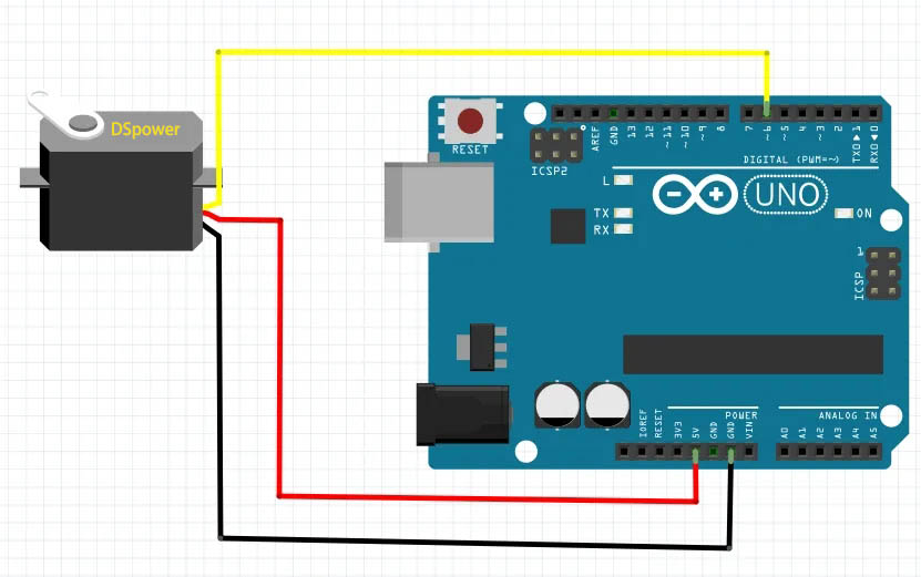
Servos have three wires that extend from the casing (See photo on the left).
Each of these wires serves a specific purpose. These three wires are for the control, power, and ground.

The control wire is responsible for supplying the electrical pulses. The motor turns to the appropriate direction as commanded by the pulses.
When the motor rotates, it changes the resistance of the potentiometer and ultimately allows the control circuit to regulate the amount of movement and direction. When the shaft is at the desired position, the supply power shuts off.
The power wire provides the servo with the power needed to operate, and the ground wire provides a connecting path separate from the main current. This keeps you from getting shocked but is not needed to run the servo.

Digital RC Servos Explained
Digital ServoA Digital RC Servo has a different way of sending pulse signals to the servo motor.
If the analog servo is designed to send a constant 50 pulse voltage per second, the digital RC servo is capable of sending up to 300 pulses per second!
With this rapid pulse signals, the speed of the motor will increase significantly, and the torque will be more constant; it decreases the amount of deadband.
As a result, when the digital servo is used, it provides quicker response and faster acceleration to the RC component.
Also, with fewer deadband, the torque also provides a better holding capability. When you operate using a digital servo, you can experience the immediate feel of the control.
Let me provide you with a case scenario. Let say you are to link a digital and analog servo to a receiver.
When you turn the analog servo wheel off-center, you will notice it responds and resists after a while – the delay is noticeable.
However, when you turn the wheel of the digital servo off-center, you will feel like the wheel and shaft responds and holds to the position that you set very quickly and smoothly.

Analog RC Servos Explained
An analog RC servo motor is the standard type of servo.
It regulates the speed of the motor by simply sending on and off pulses.
Normally, the pulse voltage is at a range between 4.8 to 6.0 volts and constant while at that. The analog receives 50 pulses for every second and when at rest, there is no voltage sent to it.
The longer the “On” pulse is being sent to the servo, the faster the motor spins and the higher the produced torque. One of the major drawbacks of the analog servo is its delay in reacting to small commands.
It does not get the motor spinning quickly enough. Plus, it also produces a sluggish torque. This situation is called “deadband”.
Post time: Jun-01-2022
